Description
John Deere TM2339 TE Gator Utility Technical Service Manual
234 pages of diagrams and photos, service and maintenance information.
File size is only 21.4 mb, so it can be downloaded in a short time over an average internet connection.
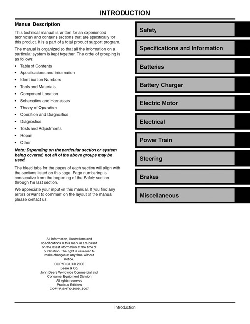
This technical manual is written for an experienced technician and contains sections that are specifically for this product. It is a part of a total product support program.
The manual is organized so that all the information on a particular system is kept together. The order of grouping is as follows:
Table of Contents
Specifications and Information
Identification Numbers
Tools and Materials
Component Location
Schematics and Harnesses
Theory of Operation
Operation and Diagnostics
Diagnostics
Tests and Adjustments
Repair
Other
Main Chapters –
Safety
Specifications and Information
Batteries
Battery Charger
Electric Motor
Electrical
Power Train
Steering
Brakes
Misc
Chapters and Sub Chapters-
Safety
Recognize Safety Information
Understand Signal Words
Replace Safety Signs
Be Prepared For Emergencies
Use Care In Handling and Servicing Batteries
Prevent Battery Explosions
Safe Charging
Prevent Acid Burns
Wear Protective Clothing
Service Machines Safely
Use Caution When Servicing Electrical System
Use Proper Tools
Park Machine Safely
Support Machine Properly And Use Proper Lifting Equipment
Work In Clean Area
Using High Pressure Washers
Illuminate Work Area Safely
Work In Ventilated Area
Handle Chemical Products Safely
Dispose of Waste Properly
Live With Safety
Specifications & Information
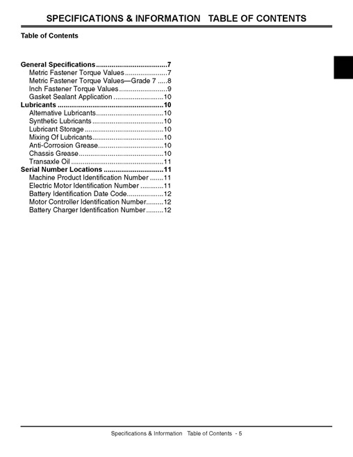
Table of Contents
General Specifications
Metric Fastener Torque Values
Metric Fastener Torque Values-Grade 7
Inch Fastener Torque Values
Gasket Sealant Application
Lubricants
Alternative Lubricants
Synthetic Lubricants
Lubricant Storage
Mixing Of Lubricants
Anti-Corrosion Grease
Chassis Grease
Transaxle Oil
Serial Number Locations
Machine Product Identification Number
Electric Motor Identification Number
Battery Identification Date Code
Motor Controller Identification Number
Battery Charger Identification Number
Batteries
Table of Contents
Specifications
Battery Specifications
Torque Specifications
Diagnostics
Troubleshooting:
Battery Position
Battery Theory and Operation
Deep Cycle Batteries
Tests and Adjustments
Battery Test
Hydrometer Test
Battery Discharge Test
Battery Test Log
Battery Maintenance
Visual Inspection
Cleaning
Water
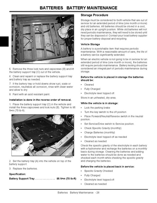
Battery Replacement
Battery Tray and Support Removal and Installation
Storage Procedure
Battery Charger
Table of Contents
Specifications
General Specifications
Torque Specifications
Component Location
Battery Charger Component Location – NA
Battery Charger Component Location – Export
W5 Charger Output Plug
W6 Charger Receptacle
Schematics and Harnesses
Battery Charger Electrical Schematic – NA
Battery Charger Electrical Schematic – Export
Theory of Operation
Battery Charger Theory of Operation
Diagnostics
Troubleshooting Battery Charging Circuit
Troubleshooting Battery Charger
Tests and Adjustments
Battery Charger Output Test
Battery Charger Relay Bypass Test – NA
Battery Charger Relay Bypass Test – Export
Rectifier Test
Fusible Link and Ammeter Test
Capacitor Test
Repair
Battery Charger Disassembly and Assembly – NA
Battery Charger Disassembly and Assembly – Export
Battery Charger Plugold-notItalic-open-TopLeftZoom-64-514-0.0
Battery Charger Receptacle
Electric Motor
Table of Contents
Specifications
Motor
Torque Specifications
Repair Specifications
Component Location
Motor Component Location
Theory of Operation
Motor Theory and Operation
Tests and Adjustments
External Motor Inspection
External Motor Test
Repair
Motor Removal and Installation
Motor Disassembly and Assembly
Inspecting Brush and Commutator
Motor Brush Spring Tension
Servicing Frame and Field Assembly
Electrical
Table of Contents
General Information
Operation and Diagnostics
Diagnostic Information
Wire Color Abbreviation Chart
Reading Electrical Schematics
Common Circuit Tests
Conductors for 12 Volt Circuits
Specifications
Motor Controller Specifications
Component Location
Electrical Component Location
Schematics and Harnesses
Schematic and Wiring Harness Legend
W1 Main Electrical Schematic
W1 Main Wiring Harness
W2 Charge Receptacle Wiring Harness
W3 Power Wiring Harness
W4 Speed Sensor Wiring Harness
W1 Main Wiring Harness Wire Color Codes
W2 Charge Receptacle Wiring Harness Wire Color Codes
W3 Power Wiring Harness Wire Color Codes
W4 Speed Sensor Wiring Harness Wire Color Codes
Theory of Operation
Motor Controller
LED Status Light Fault Codes
Clearing Fault Codes
Hand Held Tester
Fault Code Chart
Diagnostics
Diagnostic Check Points
Operation and Diagnostics
Unswitched Power Circuit Operation
Unswitched Power Circuit Schematic
Unswitched Power Circuit Diagnosis
Primary Switched Power Circuit Operation
Primary Switched Power Circuit Schematic
Primary Switched Power Circuit Diagnosis
Secondary Switched Power Circuit Operation
Secondary Switched Power Circuit Schematic
Secondary Switched Power Circuit Diagnosis
Drive Motor and Speed Sensor Circuit Operation
Drive Motor and Speed Sensor Circuit Schematic
Drive Motor and Speed Sensor Circuit Diagnosis
Park Brake Circuit Operation
Park Brake Circuit Schematic
Park Brake Circuit Diagnosis
Forward and Throttle Circuit Operation
Forward and Throttle Circuit Schematic
Forward & Throttle Circuit Diagnosis
Reverse and Throttle Circuit Operation
Reverse and Throttle Circuit Schematic
Reverse and Throttle Circuit Diagnosis
Off Seat Circuit Operation
Off Seat Circuit Schematic
Off Seat Circuit Diagnosis
Hour Meter
Hour Meter
Hour Meter
Headlight Circuit Operation
Headlight Circuit Schematic
Headlight Circuit Diagnosis
Tests and Adjustments
Battery Set Test
Electric Drive Motor Test
Key Switch Test
Functional Switches Test
Drive
Seat Switch Test
Headlight Switch Test
Motor Relay Test
Hour Meter
Motor Speed Sensor Test
Charger Interlock Switch Test
Throttle Position Sensor Test
Warning Alarm Test
Throttle Linkage and Stop Adjustment
Repair
Throttle Components Disassembly and Assembly
Horn Circuit
Horn Circuit Operation
Horn Circuit Schematic
Horn Circuit Diagnosis
Cargo Box Lift Circuit
Cargo Box Lift Circuit Operation
Cargo Box Lift Circuit Schematic
Cargo Box Lift Circuit Diagnosis
Actuator Components
Replace Actuator Clutch
Replace Motor
Cover Tube Seal
Power Train – Gear
Table of Contents
Specifications
General Specifications
Torque Specifications
Other Materials
Component Location
Transaxle Components
Axle Components
Theory of Operation
Transaxle Theory of Operation
Repair
Transaxle Removal and Installation
Axle Shaft Removal and Installation
Differential Case Disassembly and Assembly
Steering
Table of Contents
Specifications
Service and Adjustment Specifications
Torque Specifications
Component Location
Steering Component Location
Diagnostics
Troubleshooting
Steering Troubleshooting Test Points
Tests and Adjustments
Toe-In Adjustment
Steering Wheel Removal, Installation, and Adjustment
Repair
Tie Rod End Removal and Installation
Steering Assembly Removal and Installation
Spindle Shaft and Bushing Removal and Installation
Steering Rack Boot Removal and Installation
Brakes
Table of Contents
Specifications
Specifications:
Component Location
Rear Axle
Brake System
Brake Cable Component Location
Theory of Operation
Brake System
Theory:
Diagnostics
Diagnostics
Tests and Adjustments
Front Brake Cable Adjustment
Rear Brake Cable Adjustment
Park Brake Switch Adjustment
Repair
Brake Pedal Assembly Removal and Installation
Brake Shoe Removal and Installation
Front Brake Cable Removal and Installation
Rear Brake Cable Removal and Installation
Parking Brake Removal and Installation
Miscellaneous
Table of Contents
Specifications
Torque Specifications
Repair
Hood Removal and Installation
Seat Removal and Installation
Seat Base Cover Removal and Installation
Rear Cover Removal and Installation
Front Wheel Removal and Installation
Rear Wheel Removal and Installation
Front Wheel Bearing Replacement
Hitch Assembly Removal and Installation
Cargo Box Removal and Installation
Adjust Cargo Box Latch
Index






Reviews
There are no reviews yet.