
Description
John Deere TM108519 Walk Greens Mower 220 E-Cut Hybrid Technical Manual
268 pages – PDF – 61.2mb
Chapters –
TM108519 Walk Greens Mower 220 E-Cut Hybrid.
Safety.
Recognize Safety Information.
Understand Signal Words.
Replace Safety Signs.
Be Prepared for Emergencies.
Wear Protective Clothing.
Service Machines Safely.
Use Proper Tools.
Park Machine Safely.
Support Machine Properly and Use Proper Lifting Equipment.
Work in Clean Area.
Illuminate Work Area Safely.
Work in Ventilated Area.
WARNING: California Proposition 65 Warning.
Remove Paint before Welding or Heating.
Avoid Harmful Asbestos Dust.
Service Tires Safely.
Avoid Injury from Rotating Blades, Augers, and PTO Shafts.
Handle Chemical Products Safely.
Dispose of Waste Properly.
Live with Safety.
Specifications and Information.
Table of Contents.
General Specifications.
Metric Fastener Torque Values.
Metric Fastener Torque Values-Grade 7.
Inch Fastener Torque Values.
Gasket Sealant Application.
O-Ring Seal Service Recommendations.
Face Seal Fittings – Inch Stud Ends Torque.
Face Seal Fittings – Metric Stud Ends Torque.
O-Ring Face Seal Fittings.
O-Ring Boss Fittings.
Fuels and Lubricants.
Gasoline.
Gasoline Storage.
Engine Oil.
Engine Break-in Oil.
Alternative Lubricants.
Synthetic Lubricants.
Lubricant Storage.
Mixing Of Lubricants.
Grease.
Transmission and Hydraulic Oil.
Serial Number Locations.
Record Identification Numbers.
Machine Identification Number.
Engine Serial Number.
Carburetor Identification Number.
Engine – Gas.
Table of Contents.
Specifications.
General Specifications.
Test and Adjustment Specifications.
Repair Specifications.
Tools and Materials.
Special or Essential Tools.
Other Materials.
Component Location and Operation.
External Engine Components.
Internal Engine Components.
Lubrication System Operation.
Cooling System Operation.
Diagnostics.
Engine Cranks But Will Not Start.
Engine Runs Poorly at Low RPM.
Engine Runs Poorly at High RPM.
Excessive Oil Consumption.
Engine Overheats.
Excessive Fuel Consumption.
Tests and Adjustments.
Check and Adjust Throttle Cable.
Adjust Slow Idle Speed.
Adjust Governor and Fast Idle Speed.
Test Cylinder Compression Pressure.
Check and Adjust Valve Clearance.
Test Spark.
Adjust Spark Plug Gap.
Adjust Alternator Belt.
Repair.
Remove and Install Fuel Tank.
Remove and Install Fuel Filter.
Remove and Install Throttle Cable.
Remove and Install Muffler.
Remove and Install Engine.
Remove and Install Air Cleaner Assembly.
Service of Air Cleaner.
Remove and Install Throttle Plate Assembly.
Remove and Install Carburetor.
Disassemble and Assemble Carburetor.
Clean and Inspect Carburetor.
Replace Pilot Screw and Limiter Cap.
Adjust Float Level.
Remove and Install Blower Housing Assembly.
Remove and Install Recoil Starter.
Disassemble and Inspect Recoil Starter.
Assemble Recoil Starter.
Remove and Install Ignition Coil.
Adjust Air Gap.
Test Ignition Coil.
Remove and Install Flywheel.
Remove and Install Rocker Arm Cover.
Remove and Install Cylinder Head and Valves.
Disassemble and Assemble Cylinder Head and Valves.
Inspect Cylinder Head and Valves.
Replace Valve Guide.
Analyze Valves.
Recondition Valve Seats.
Lap Valves.
Remove and Install Crankcase Cover.
Replace Bearing and Oil Seal.
Remove and Install Camshaft and Tappets.
Inspect Camshaft and Tappets.
Remove Piston and Connecting Rod.
Inspect Piston and Connecting Rod.
Disassemble Piston and Connecting Rod.
Assemble Piston and Connecting Rod.
Inspect Piston and Connecting Rod.
Check Connecting Rod Side Play.
Check Connecting Rod-to-Crankshaft Clearance.
Check Piston Ring End Gap.
Analyze Piston Ring Wear.
Analyze Piston Wear.
Remove and Install Crankshaft.
Inspect Crankshaft.
Replace Timing-Governor Gear.
Analyze Crankshaft and Connecting Rod Wear.
Inspect Cylinder Block.
Crankshaft Bearing Inspection and Replacement.
Replace Oil Seal.
Deglaze Cylinder Bore.
Rebore Cylinder Block.
Remove and Install Governor.
Electrical.
Table of Contents.
Information.
Reading Electrical Schematics.
Theory Of Operation Information.
Diagnostic Information.
Wire Color Abbreviation Chart.
Common Circuit Tests.
Conductors For 12 Volt Circuits.
Specifications.
General Specifications.
Tools and Materials.
Tools.
Materials.
Component Location.
Engine Components.
Reel Motor Controller.
Reel Motor.
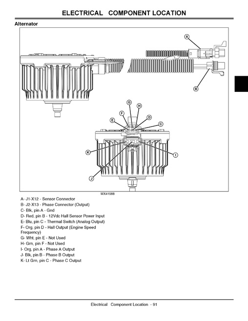
Alternator.
Schematics and Harnesses.
Schematic and Harness Legend.
Main Electrical Schematic.
W1 Upper Wiring Harness.
W2 Lower Wiring Harness.
W1 Upper Wire Color Codes.
W2 Lower Wire Color Codes.
W3 Rectifier Wiring Harness.
W3 Wire Color Codes.
W4 Auxiliary Light Wiring Harness [Optional].
W4 Wire Color Codes.
Operation and Diagnostics.
Power Circuit Operation.
Power Circuit Schematic.
System: Power Supply Diagnostic Check.
Ignition Circuit Operation – Engine Shutting Off.
Ignition Circuit Schematic.
System: Ignition Circuit Diagnosis.
Symptom: Engine Won’t Start or Feels Loaded While Starting.
Electronic Controllers.
Data Bus Systems.
CAN Bus Theory of Operation.
CAN Network Voltage Checks.
Troubleshooting Electronic Controllers.
Accessing Addresses and Diagnostic Trouble Codes.
Approved Software for Control Unit.
Controller and Motor Diagnostics.
Electronic Controller Theory of Operation.
Diagnostic LED Blink Codes (Fault Codes).
Reel Motor Theory of Operation.
Reel Motor Controller Signals.
Alternator Signals.
Operating Conditions.
Diagnostic LED Fault Codes.
Symptom: Diagnostic LED Fault Codes.
DTC Error Codes Table.
System: DTC Readings.
WBG_000628.12 Stuck in Boot Block (Blink Code SOLID ON).
WBG_002513.03 (Blink Code 7-3) – Orange Phase (A) is Shorted to Supply.
WBG_002513.04 (Blink Code 7-2) – Orange Phase (A) is Shorted to Ground.
WBG_002513.05 (Blink Code 7-4) – Orange Phase (A) is Open.
WBG_002514.03 (Blink Code 7-3) – Black Phase (B) is Shorted to Supply.
WBG_002514.04 (Blink Code 7-2) – Black Phase (B) is Shorted to Ground.
WBG_002514.05 (Blink Code 7-4) – Black Phase (B) is Open.
WBG_002515.03 (Blink Code 7-3) – Green Phase (C) is Shorted to Supply.
WBG_002515.04 (Blink Code 7-2) – Green Phase (C) is Shorted to Ground.
WBG_002514.05 (Blink Code 7-4) – Green Phase (C) is Open.
WBG_003353.00 (Blink Code 8-1) – Alternator Over Temp Threshold.
WBG_003353.01 (Blink Code 8-3) – Alternator Hall Loss.
WBG_003509.00 (Blink Code 7-5) – Pot Signal Voltage High.
WBG_003509.01 (Blink Code 7-5) – Pot Signal Voltage Low.
WBG_003510.00 (Blink Code 9-7) – Pot Supply Voltage High.
WBG_003510.01 (Blink Code 9-7) – Pot Supply Voltage Low.
WBG_003511.00 (Blink Code 9-5) – Hall Voltage High.
WBG_003511.01 (Blink Code 9-5) – Hall Voltage Low.
WBG_003597.00 (Blink Code 9-3) – Controller 14V High.
WBG_003597.01 (Blink Code 9-3) – Controller 14V Low.
WBG_521153.00 (Blink Code NONE) – Manufacturer Service Code.
WBG_521153.15 (Blink Code 2-9) – Controller Shutdown Over Temp.
WBG_522327.00 (Blink Code 2-10) – Motor Over Temp.
WBG_522917.00 (Blink Code 2-5) – Controller Current Threshold 3 Shutdown.
WBG_522917.06 (Blink Code 2-8) – Controller Hardware Current Shutdown.
WBG_522917.15 (Blink Code 2-5) – Controller Current Threshold 1 Shutdown.
WBG_522917.16 (Blink Code 2-5) – Controller Current Threshold 2 Shutdown.
WBG_522918.00 (Blink Code 1-5) – Motor Start Failed 3x Fault.
WBG_522918.02 (Blink Code 1-10) – Motor Spin Direction Shutdown.
WBG_522918.15 (Blink Code 1-6) – Motor Stalled While Running.
WBG_522919.02 (Blink Code NONE) – Manufacturer Service Code.
WBG_522919.03 (Blink Code 6-6) – Hall Resync Shutdown.
WBG_522919.04 (Blink Code NONE) – Manufacturer Service Code.
WBG_522919.08 (Blink Code NONE) – Manufacturer Service Code.
WBG_522919.09 (Blink Code NONE) – Manufacturer Service Code.
WBG_522919.12 (Blink Code 6-4) – Invalid Hall State Detected at Start-Up.
WBG_522937.02 (Blink Code 8-2) – Frequency of Clip Shutdown.
WBG_522976.12 (Blink Code 8-4) – Incorrect Application Software.
WBG_523666.00 (Blink Code 9-2) – Bus Voltage High.
WBG_523666.01 (Blink Code 1-7) – Bus Voltage Low.
WBG_523666.02 (Blink Code 1-7) – Low VBUS on Start.
WBG_523666.15 (Blink Code NONE) – Manufacturer Service Code.
Tests and Adjustments.
Backlap Switch Test.
Run.
Park Brake Switch Test.
Clutch Switch Test.
Test Flywheel Magnet.
Reel Motor Test.
Reel Motor Wiring.
Frequency of Cut (FOC) Potentiometer Test.
Bridge Rectifier Test.
Power Train.
Table of Contents.
Specifications.
Adjustment Specifications.
Repair Specifications.
Tools.
Component Location and Operation.
Drive Belt and Differential System.
Gear Case Components.
Traction Roller Components.
Diagnostics.
Symptom: Machine Will Not Drive.
Symptom: Noisy Operation.
Symptom: Machine Does Not Reach Full Ground Speed.
Symptom: Machine Speed is Erratic.
Symptom: Traction Drive Pulls to One Side.
Symptom: Park Brake Does Not Hold Machine.
Tests and Adjustments.
Drive Belt Tension Check and Adjustment.
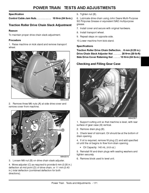
Traction Roller Drive Chain Slack Adjustment.
Checking and Filling Gear Case.
Repair.
Clutch Control Cable Replacement.
Traction Drive Belt Replacement.
Alternator Drive Belt Replacement.
Alternator Sheave Removal and Replacement.
Differential Gear Case Removal and Installation.
Differential Gear Case Disassembly and Inspection.
Differential Gear Case Assembly.
Traction Roller Assembly Removal and Installation.
Handlebar and Controls.
Table of Contents.
Component Location.
Controls.
Clutch Control and Operator Presence Bail.
Brake Control and Throttle Lever.
Diagnostics.
Symptom: Clutch Control Does Not Fully Disengage.
Symptom: Brake Control Does Not Fully Disengage.
Symptom: Operator Presence Bail Does Not Return Fully.
Handlebar Control Adjustments.
Throttle Lever Tension Adjustment.
Throttle Lever Travel Adjustment.
Operator Presence Bail Adjustment.
Park Brake Switch Adjustment.
Clutch Switch Adjustment.
Handlebar Height Adjustment.
Repair.
Remove and Install Handlebar Cover.
FOC Potentiometer Replacement.
Handlebar Assembly Removal and Installation.
Brakes.
Table of Contents.
Specifications.
Specifications.
Component Location and Operation.
Brake System Operation.
Diagnostics.
Symptom: Machine Cannot Be Moved.
Symptom: Brake Does Not Engage With Control Lever in Brake Position.
Symptom: Brake Does Not Hold Machine.
Symptom: Excessive Brake Wear.
Checks and Adjustments.
Park Brake Adjustment.
Repair.
Replace Park Brake Cable.
Park Brake Band Replacement.
Attachments.
Table of Contents.
Specifications.
General Specifications.
Adjustment Specifications.
Repair Specifications.
Tools and Materials.
Special or Essential Tools.
Dealer Fabricated Tools.
Other Materials.
Component Location.
Cutting Unit – QA-5.
Greens Tender Conditioner (GTC).
Theory of Operation.
Reel and Bed Knife Grinding.
Rollers.
Performance Variables.
Diagnostics.
Marcelling.
Streaking.
Height-of-Cut (HOC) Changes.
Poor Quality of Cut.
Reel Does Not Rotate.
Unit Not Cutting.
Tests and Adjustments.
Adjusting Frequency of Clip (FOC).
Adjust Bed Knife-to-Reel.
Adjusting Bed Knife and Bed Knife Shoe Position for Worn Reel (QA-5 Reel).
Backlapping Cutting Unit.
Grinding Reel and Bed Knife.
Adjust Height-of-Cut Range (QA-5 Reel).
Adjust Height-of-Cut (HOC) (QA-5 Reel).
Adjust Cutting Shield.
Adjust Front Roller (QA-5 Reel).
Adjusting Greens Tender Conditioner (GTC).
Repair.
Inspect Reel and Bed Knife.
Remove and Install Electric Reel Motor.
Removing and Installing Cutting Units.
Adjusting Cutting Unit Limit Chains.
Reel Motor Drive Belt Removal and Installation.
Reel Removal and Installation (QA-5 Reel).
Remove and Install Bed Knife – QA-5 Reel.
Remove and Install Front Roller – QA-5 Reel.
Repair Front Roller.
Remove and Install Rear Roller – QA-5 Reel.
Remove and Install Greens Tender Conditioner.
Disassemble and Inspect Greens Tender Conditioner.
Miscellaneous.
Table of Contents.
Tools and Materials.
Other Materials.
Repair.
Remove and Install Transport Wheel.
Frame and Drive Covers.
Index.


Reviews
There are no reviews yet.