Description
John Deere TM108119 2500B 2500E Hybrid Riding Greens Mower SN030001 Technical Manual
764 pages – pdf – 109mb
Includes –
TM108119 Riding Greens Mower.
2500B and 2500E Hybrid (SN 030001-).
Introduction.
Introduction.
Manual Description.
Safety.
Recognize Safety Information.
Understand Signal Words.
Replace Safety Signs.
Handle Fluids Safely – Avoid Fires.
Use Care In Handling and Servicing Batteries.
Prevent Battery Explosions.
Prevent Acid Burns.
Wear Protective Clothing.
Use Care Around High-Pressure Fluid Lines.
Service Machines Safely.
Use Proper Tools.
Park Machine Safely.
Support Machine Properly and Use Proper Lifting Equipment.
Work In Clean Area.
Using High Pressure Washers.
Illuminate Work Area Safely.
Work In Ventilated Area.
Warning: California Proposition 65 Warning.
Remove Paint Before Welding or Heating.
Avoid Harmful Asbestos Dust.
Service Tires Safely.
Avoid Injury From Rotating Blades, Augers and PTO Shafts.
Service Cooling System Safely.
Handle Chemical Products Safely.
Dispose Of Waste Properly.
Live With Safety.
Specifications and Information.
Table of Contents.
General Information.
Metric Fastener Torque Values.
Metric Fastener Torque Values – Grade 7.
Inch Fastener Torque Values.
O-Ring Seal Service Recommendations.
Using Proper Fuel.
Engine Oil.
Hydrostatic Transmission and Hydraulic Oil.
Biodegradable Oil.
Converting From HY-GARD to BIO HY-GARD.
Grease.
Alternative Lubricants.
Synthetic Lubricants.
Lubricant Storage.
Mixing of Lubricants.
Oil Filters.
Engine Coolant.
Engine Coolant Drain Interval.
Identification Numbers.
Machine Identification Number Locations.
Engine – Gas.
Table of Contents.
Specifications.
General Specifications.
Tests and Adjustments Specifications.
Repair Specifications.
Torque Specifications (Alphabetical).
Tools and Materials.
Gas Engine.
Component Location.
Exterior Engine Component Location.
Theory of Operation.
Cooling System Operation.
Ignition System Operation.
Fuel Supply and Air Intake System Operation.
Carburetor Operation.
Crankcase Breather Operation.
Governor Operation.
Automatic Compression Release (ACR) Operation.
Lubrication System Operation.
Diagnostics.
Engine Diagnosis.
Symptom: Engine Cranks but Will Not Start.
Symptom: Engine Malfunctions at Low RPM.
Symptom: Engine Malfunctions at High RPM.
Symptom: Excessive Oil Consumption.
Symptom: Engine Overheats.
Symptom: Excessive Fuel Consumption.
Tests and Adjustments.
Test Spark.
Adjust Throttle Cable.
Adjust Choke Cable.
Adjust Slow Idle Speed.
Adjust Fast Idle Speed.
Check Compression.
Check and Adjust Valve Clearance.
Test Crankcase Vacuum.
Test Engine Oil Pressure.
Test Fuel Flow.
Test Fuel Pressure.
Check and Adjust Fan Belt Tension – 2500B.
Check and Adjust 48V Alternator Drive Belt Tension – 2500E.
Radiator Bubble Test.
Pressure Test Radiator Cap.
Test Thermostat.
Coolant Temperature Switch Test.
Test Cooling System.
Spark Plug Gap Adjustment.
Starting Motor – No-Load Amperage Draw and RPM Test.
Repair.
Service Cooling System.
Remove and Install Fan Belt – 2500B.
Remove and Install 48V Alternator Belt – 2500E.
Remove, Inspect, and Install 48V Alternator Belt Tensioner.
Remove and Install 48V Alternator.
Remove and Install Thermostat.
Remove and Install Coolant Temperature Switch.
Remove and Install Cooling Fan.
Remove and Install Fan Mounting Bracket.
Remove and Install Bearing – Fan Mounting Bracket.
Remove and Install Coolant Pump.
Disassemble, Inspect, and Assemble Coolant Pump.
Remove and Install Radiator.
Inspect Radiator.
Remove and Install Muffler.
Remove and Install Air Cleaner.
Remove and Install Fuel Pump.
Remove and Install Throttle Lever and Cable.
Remove and Install Choke Cable.
Remove and Install Carburetor.
Disassemble and Assemble Carburetor.
Carburetor – Clean, Inspect and Rebuild.
Carburetor – Float Level Adjustment.
Remove and Install Intake Manifold.
Intake Manifold – Inspection.
Remove and Install Rocker Arm Covers.
Remove and Install Rocker Arm Assembly.
Inspect Rocker Arm Assembly.
Inspect Push Rod.
Remove and Install Cylinder Head.
Disassemble and Assemble Cylinder Head and Valves.
Inspect Cylinder Head and Valves.
Analyze Valves.
Recondition Valve Seats.
Lap Valves.
Remove and Install Engine.
Remove, Inspect, and Install Flywheel.
Remove and Install Stator.
Remove and Install Breather.
Remove, Inspect, and Install Crankcase Cover.
Crankcase Cover – Oil Seal Replacement.
Remove and Install Governor Arm.
Remove and Install Piston and Connecting Rod.
Disassemble, Inspect, and Assemble Piston and Connecting Rod.
Analyze Piston Ring Wear.
Analyze Piston Wear.
Cylinder Bore Honing.
Cylinder Bore Resizing.
Remove and Install Camshaft and Tappet.
Inspect Camshaft.
Remove and Install Crankshaft.
Inspect Crankshaft.
Regrind Crankshaft.
Replace Crankshaft Oil Seals.
Analyze Crankshaft and Connecting Rod Wear.
Inspect Cylinder Block.
Remove and Install Oil Pump and Oil Pickup.
Disassemble and Assemble Oil Pump and Oil Pickup.
Inspect Oil Pump and Oil Pickup.
Remove and Install Governor Assembly.
Remove and Install Governor Cross Shaft.
Remove and Install Ignition Coil.
Remove and Install Pulser Coil.
Remove and Install Starting Motor.
Disassemble, Inspect, and Assemble Starting Motor.
Engine – Diesel.
Table of Contents.
Specifications.
General Specifications.
Test and Adjustment Specifications.
Repair Specifications.
Torque Specifications.
Tools and Materials.
Special or Required Tools.
Other Material.
Theory of Operation.
Cooling System Operation.
Lubrication System Operation.
Fuel and Air System Operation.
Diesel Engine Troubleshooting.
Use of Dielectric Grease.
Symptom: Engine Will Not Start.
Symptom: Engine Starts but Does Not Continue Running – No Exhaust Smoke.
Symptom: Engine Starts but Does Not Continue Running – Excess Exhaust Smoke.
Symptom: Low Engine Output – Exhaust Color NORMAL.
Symptom: Low Engine Output – Exhaust Color WHITE.
Symptom: Low Engine Output – Exhaust Color BLACK.
Symptom: Exhaust Color WHITE Under Load.
Symptom: Exhaust Color BLACK Under Load.
Symptom: Exhaust Temperature Too High.
Symptom: Engine Runs Rough – Misfiring.
Symptom: Engine Runs Rough – Uneven Combustion Sound.
Symptom: Engine Runs Rough – Engine Surges DURING IDLING.
Symptom: Engine Runs Rough – Engine Surges UNDER LOAD.
Symptom: Engine Runs Rough – Excessive Engine Vibration.
Symptom: Excessive Fuel Consumption.
Symptom: Excessive Oil Consumption.
Symptom: Fuel Oil in Crankcase.
Symptom: Coolant in Crankcase.
Symptom:Low Oil Pressure.
Symptom: Engine Is Overheating.
Symptom: Low Engine Coolant Temperature.
Symptom: Low Compression.
Starting Motor Diagnostics.
Symptom: Starter Does Not Rotate.
Starter Rotates Slowly.
Symptom: Starter Rotates but Does Not Crank.
Tests and Adjustments.
Check and Adjust 12V Alternator Drive Belt Tension – 2500B.
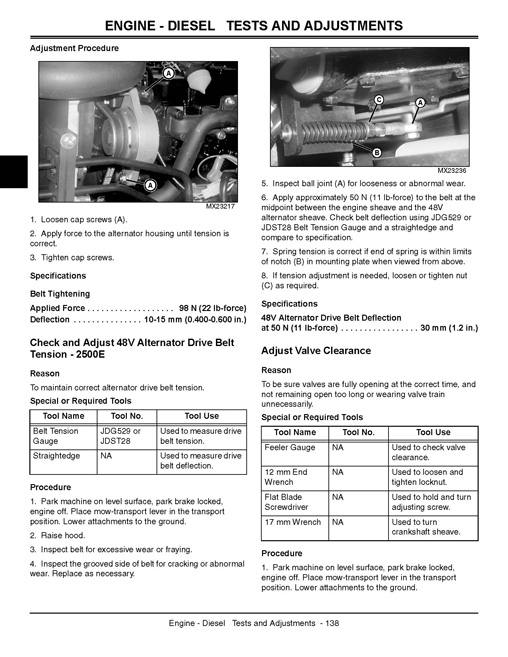
Check and Adjust 48V Alternator Drive Belt Tension – 2500E.
Adjust Valve Clearance.
Check Valve Lift.
Test Cylinder Compression.
Test Engine Oil Pressure.
Leak Test Air Intake System.
Test Fuel Transfer Pump Pressure.
Test Fuel Transfer Pump Flow.
Leak Test Fuel System.
Bleed Fuel System.
Adjust Slow Idle Speed.
Adjust Throttle Cable.
Fast Idle Speed Check.
Test Fuel Injection System.
Test Fuel Injection Nozzle.
Injection Pump Static Timing Check.
Pressure Test Cooling System.
Pressure Test Radiator Cap.
Test Thermostat.
Repair.
Remove and Install 12V Alternator Drive Belt – 2500B.
Remove and Install 48V Alternator Drive Belt – 2500E.
Remove and Install 48V Alternator Belt Tensioner – 2500E.
Remove and Install Throttle Cable Assembly.
Remove, Inspect and Install Radiator.
Remove and Install Air Filter Restriction Indicator.
Remove and Install Air Cleaner Assembly.
Remove and Install Muffler.
Remove and Install Exhaust Manifold.
Remove and Install Thermostat.
Remove and Install Coolant Temperature Switch.
Fill Cooling System.
Remove and Install Engine.
Remove and Install Glow Plug.
Remove and Install Intake Manifold.
Remove and Install Rocker Arm Assembly.
Disassemble and Assemble Rocker Arm Assembly.
Remove and Install Cylinder Head.
Recondition Cylinder Head.
Measure Piston-to-Cylinder Head Clearance.
Remove and Install Piston and Connecting Rod.
Connecting Rod Side Play Check.
Check Connecting Rod Bearing Clearance.
Cylinder Bore.
Crankshaft Rear Oil Seal.
Crankshaft Front Oil Seal.
Crankshaft End Play Check.
Crankshaft and Main Bearings.
Crankshaft Main Bearing Clearance Check.
Remove and Install Flywheel.
Remove and Install Flywheel Housing.
Camshaft.
Remove, Inspect and Install Camshaft Follower.
Remove and Install Timing Gear Cover.
Remove and Install Idler Gear.
Remove and Install Timing Gear Housing.
Oil Pan, Crankcase Extension and Pickup Tube.
Oil Pump.
Remove and Install Coolant Pump (Thermostat Included).
Remove and Install Fuel Filter and Water Separator Assembly.
Assemble Fuel Filter and Water Separator.
Remove and Install Fuel Injection Pump.
Remove, Inspect and Install Fuel Injection Nozzle.
Remove and Install Fuel Shutoff Solenoid.
Remove and Install Fuel Transfer Pump.
Remove and Install Starting Motor.
Remove and Install Starting Motor Solenoid.
Remove and Install 48V Alternator – 2500E.
Remove and Install 12V Alternator.
Electrical.
Table of Contents.
Specifications.
Test Specifications.
Tools.
General Information.
Theory of Operation Information.
Diagnostic Information.
Common Circuit Tests.
Reading Electrical Schematics.
Wire Color Abbreviation Chart.
Component Location.
Gasoline Engine Model 2500B (Page 1 of 2).
Gasoline Engine Model 2500E.
Diesel Engine Model 2500B.
Diesel Engine Model 2500E (Page 1 of 2).
Instrument Cluster – A7.
Schematics and Harnesses.
Schematic and Wiring Harness Legend – Gasoline Engine Models.
Main Electrical Schematic – 2500B .
Main Wiring Harness (W1) – Gasoline Engine (1 of 4).
Main Wiring Harness (W1) – Gasoline Engine Wire Code Table.
Gasoline Engine Wiring Harnesses.
Fuel Pump Harness (W14).
Fuel Pump Harness (W14) – Wire Code Table.
Schematic and Wiring Harness Legend – Diesel Engine Models.
Main Electrical Schematic – 2500B .
Main Wiring Harness (W1) – Diesel Engine (1 of 4).
Main Wiring Harness (W1) – Diesel Engine Wire Code Table.
Optional Third Wheel Assist Wiring Harness (W11).
Optional Third Wheel Assist Wiring Harness (W11) – Wire Code Table.
Lighting Wiring Harness (W12).
Lighting Wiring Harness (W12) – Wire Code Table.
Reel Motor Control Module Signal Harness (W15).
Reel Motor Control Module Signal Wiring Harness (W15) Wire Code Table – Model 2500E.
Reel Motor Power Harness (W17).
Reel Motor Power Wiring Harness (W17) Wire Code Table – Model 2500E.
Operation and Diagnostics – Gasoline Engine.
Diagnostic Codes.
Power Circuit Operation – Unswitched.
Power Circuit Operation – Switched.
Power Circuit Schematic.
System: Power Circuit Diagnosis – Unswitched.
System: Power Circuit Diagnosis – Switched.
Cranking Circuit Operation.
Cranking Circuit Schematic.
System: Cranking Circuit Diagnosis.
Run Circuit Operation – Operator On Seat.
Run Circuit Schematic – Operator On Seat.
Run Circuit Operation – Operator Off Seat.
Run Circuit Schematic – Operator Off Seat.
Run Circuit Operation – Engine Shutdown.
Run Circuit Schematic – Engine Shutdown.
System: Run Circuit Diagnosis.
Raise-Lower Circuit Operation.
Raise-Lower Circuit Schematic.
System: Raise-Lower Circuit Diagnosis.
Mow Circuit Operation 2500B.
Mow Circuit Schematic 2500B.
System: Mow Circuit Diagnosis – Model 2500B.
Backlap Circuit Operation 2500B.
Backlap Circuit Schematic 2500B.
System: Backlap Circuit Diagnosis – Model 2500B.
Mow Circuit Operation 2500E.
Mow Circuit Schematic 2500E.
Backlap Circuit Operation 2500E.
Backlap Circuit Schematic 2500E.
Mow-Backlap Circuit Diagnosis – Model 2500E.
System: Reel Motor Circuit Diagnosis – Model 2500E.
Charging Circuit Operation.
Charging Circuit Schematic.
System: Charging Circuit Diagnosis.
Engine Oil Pressure Circuit Operation.
Engine Oil Pressure Circuit Schematic.
System: Engine Oil Pressure Circuit Diagnosis.
Engine Coolant Temperature Circuit Operation.
Engine Coolant Temperature Circuit Schematic.
System: Engine Coolant Temperature Circuit Diagnosis.
Hydraulic Oil Temperature Circuit Operation.
Hydraulic Oil Temperature Circuit Schematic.
System: Hydraulic Oil Temperature Circuit Diagnosis.
Hour Meter Circuit Operation.
Hour Meter Circuit.
System: Hour Meter Circuit Diagnosis.
Lighting Circuit Operation.
Lighting Circuit Schematic.
System: Lighting Circuit Diagnosis.
Operation and Diagnostics – Diesel Engine.
Diagnostic Codes.
Power Circuit Operation – Unswitched.
Power Circuit Operation – Switched.
Power Circuit Schematic.
System: Power Circuit Diagnosis – Unswitched.
System: Power Circuit Diagnosis – Switched.
Cranking Circuit Operation.
Cranking Circuit Schematic.
System: Cranking Circuit Diagnosis.
Run Circuit Operation.
Run Circuit Schematic – Operator On Seat.
Run Circuit Schematic – Operator Off Seat.
System: Run Circuit Diagnosis.
Raise-Lower Circuit Operation.
Raise-Lower Circuit Schematic.
System: Raise-Lower Circuit Diagnosis.
Mow Circuit Operation – Model 2500B.
Mow Circuit Schematic – Model 2500B.
System: Mow Circuit Diagnosis – Model 2500B.
Backlap Circuit Operation – Model 2500B.
Backlap Circuit Schematic – Model 2500B.
System: Backlap Circuit Diagnosis – Model 2500B.
Mow Circuit Operation – Model 2500E.
Mow Circuit Schematic – Model 2500E.
Backlap Circuit Operation – Model 2500E.
Backlap Circuit Schematic – Model 2500E.
System: Mow-Backlap Circuit Diagnosis – Model 2500E.
System: Reel Motor Circuit Diagnosis – Model 2500E.
Glow Plug Circuit Operation.
Glow Plug Circuit Schematic.
System: Glow Plug Circuit Diagnosis.
Charging Circuit Operation.
Charging Circuit Schematic.
System: Charging Circuit Diagnosis.
Engine Oil Pressure Circuit Operation.
Engine Oil Pressure Circuit Schematic.
System: Engine Oil Pressure Circuit Diagnosis.
Engine Coolant Temperature Circuit Operation.
Engine Coolant Temperature Circuit Schematic.
System: Engine Coolant Temperature Circuit Diagnosis.
Hydraulic Oil Temperature Circuit Operation.
Hydraulic Oil Temperature Circuit Schematic.
System: Hydraulic Oil Temperature Circuit Diagnosis.
Hour Meter Circuit Operation.
Hour Meter Circuit Schematic.
System: Hour Meter Circuit Diagnosis.
Lighting Circuit Operation.
Lighting Circuit Schematic.
System: Lighting Circuit Diagnosis.
Tests and Adjustments.
Ground Circuit Test.
Interlock Module Check.
Battery Test.
Charge Battery.
Battery Load Test.
Regulated Voltage Output Test.
Unregulated Voltage Output Test- Gasoline Engine.
Unregulated Voltage Output Test – Diesel Engine.
Starting Motor Cranking Amperage Draw Test.
Starting Motor Solenoid Test – Gasoline Engine.
Starting Motor Solenoid Test- Diesel Engine.
Pulser Coil Test- Gasoline Engine.
Ignition Coil Test – Gasoline Engine.
Ignition Module Test – Gasoline Engine.
Glow Plug Test – Diesel.
Fuse Test.
Diode Test.
Resistor Test.
Electrical Relay Test.
Key Switch Test.
Park Brake and Mow-Transport Switch Test.
Raise-Lower Switch Test.
Seat Switch Test.
Mow Solenoid Test.
Raise or Lower Solenoid Test.
Backlap Switch Test – Model 2500B.
Backlap Switch Test- Model 2500E.
Hydraulic Temperature Switch Test.
Engine Oil Pressure Switch Test – Gasoline Engine.
Fuel Shutoff Solenoid Test – Gasoline Engine.
Fuel Shutoff Solenoid Test – Diesel Engine.
Engine Oil Pressure Switch Test – Diesel Engine.
Headlight Switch Test (Optional).
Reel Motor Forward-Reverse Switch Test – Model 2500E.
Reel Motor Speed Control Test – Model 2500E.
Engine Coolant Temperature Switch Test.
Reel Motor Test – Model 2500E.
Reel Motor Power Draw Test – Model 2500E.
Repair.
Remove and Install Battery.
Clean Battery.
Remove METRI-PACK.
Replace METRI-PACK.
Remove WEATHER PACK.
Repair Reel Motor Wiring Harness.
Hydrostatic Power Train.
Table of Contents.
Specifications.
Test and Adjustment Specifications.
Repair Specifications.
Tools and Materials.
Tools.
Materials.
Component Location.
Hydrostatic Drive Components.
Hydraulic System Hose Routing – Motor Drive System.
Theory of Operation.
Hydrostatic Transmission.
Hydrostatic Schematics.
Main Hydrostatic Diagram.
Third Wheel Assist Hydrostatic Diagram.
Diagnostics.
Troubleshooting Hints.
Symptom:Mower Will Not Move in Forward or Reverse.
Symptom:Mower Will Not Reach Full Speed.
Symptom:Sluggish Response to Acceleration or Deceleration, and Hill Climbing.
Symptom:Noisy Pump.
Tests and Adjustments.
Test Charge Pressure.
Test Hydrostatic Transmission Pump Flow.
Adjust Hydrostatic Pump Control Linkage.
Mowing Speed Adjustment.
Repair.
Remove and Install Mow-Transport Cable and Lever Assembly.
Mow-Transport Switch and Lever Repair.
Remove and Install Hydrostatic Pump Control Cable.
Forward and Reverse Travel Pedal Repair.
Remove and Install Hydrostatic Pump Assembly – Gasoline Engine.
Remove and Install Hydrostatic Pump Assembly – Diesel Engine.
Disassemble Hydrostatic Pump.
Inspect Hydrostatic Pump.
Assemble Hydrostatic Pump.
Remove and Install Front Wheel Motors.
Remove and Install Third Wheel Assist Motor.
Disassemble and Inspect Wheel Motors.
Assemble Wheel Motors.
Wheel Motor Final Checks.
Remove and Install Third Wheel Assist Valve.
Repair Third Wheel Assist Drive Valve.
Hydraulics.
Table of Contents.
Specifications.
Test and Adjustment Specifications.
Repair Specifications.
Tools and Materials.
Tools.
Component Location.
Hydraulic System Component Location.
Hydraulic System Hose Routing – Steering System.
Hydraulic System Hose Routing – Reel Drive System – 2500B.
Hydraulic System Hose Routing – Cutting Unit Lift System.
Schematics and Harnesses.
JIC Hydraulic Circuit Symbols.
Hydraulic System Schematic.
Hydraulic System Schematic – With Optional Equipment.
Operation and Diagnostics.
Reel Drive System – Mow Operation – 2500B.
Reel Drive System – Backlap Operation – 2500B.
Cutting Unit Lift System Operation – Raise.
Cutting Unit Lift System Operation – Lower and Float.
Leak Detection System Operation (Optional).
System: Reel Drive Diagnosis – 2500B.
System: Lift System Diagnosis.
Tests and Adjustments.
Warm Up Hydraulic Oil.
Bleed Hydraulic System.
Test Lift Pump Oil Flow.
Test Reel Drive Pump Oil Flow – 2500B.
Test Reel Motor Case Drain.
Test and Adjust Mow Valve Relief Valve – 2500B.
Adjust Front Lift Arm.
Adjust Rear Lift Arm.
Repair.
Remove and Install Hydraulic Reservoir Expansion Tank.
Remove and Install Hydraulic Reservoir.
Remove and Install Oil Cooler – 2500B.
Remove and Install Raise-Lower Lever Assembly.
Repair Raise-Lower Lever Assembly.
Remove and Install Hydraulic Pump Assembly.
Disassemble and Inspect Hydraulic Pump Assembly.
Assemble Hydraulic Pump Assembly.
Remove and Install Reel Motor – QA-5 Reel.
Disassemble and Inspect Reel Motor – QA-5 Reel.
Assemble Reel Motor – QA-5 Reel.
Remove and Install Mow-Backlap Valve.
Disassemble and Assemble Mow-Backlap Valve.
Remove and Install Lift Valve.
Disassemble and Assemble Lift Valve.
Remove and Install Front Lift Cylinder.
Disassemble and Assemble Front Lift Cylinder.
Remove and Install Center (Rear) Lift Cylinder.
Disassemble and Assemble Center (Rear) Lift Cylinder.
Repair Center (Rear) Lift Arm.
Repair Center (Rear) Lift Arm.
Repair Front Lift Arms – QA-5 Reels.
Brakes.
Table of Contents.
Specifications.
Adjustment Specifications.
Repair Specifications.
Component Location.
Brake System Component Location.
Theory of Operation.
Brake System Operation.
Diagnostics.
Symptom: Machine Will Not Move.
Symptom: Brake Will Not Lock or Hold Machine.
Symptom: Excessive Brake Wear.
Tests and Adjustments.
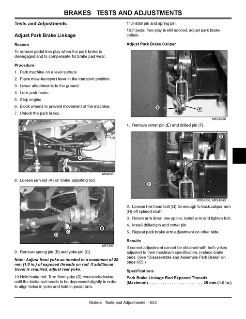
Adjust Park Brake Linkage.
Adjust Park Brake Switch.
Repair.
Remove and Install Park Brake.
Disassemble and Assemble Park Brake.
Disassemble and Assemble Park Brake Pedal and Lock Linkage.
Disassemble and Assemble Park Brake Linkage.
Steering.
Table of Contents.
Specifications.
Test and Adjustment Specifications.
Repair Specifications.
Tools and Materials.
Special or Essential Tools.
Other Materials.
Component Location.
Steering System Component Location.
Theory of Operation.
Steering System Operation – Neutral.
Steering System Operation – Power Turn.
Steering System Operation – Manual Turn.
Diagnostics.
Symptom: Steering Not Driving Straight.
Symptom: Steering Wheel Vibration.
Symptom: Sluggish Steering Response.
Symptom: High Steering Effort in Both Directions.
Symptom:Steering Effort Is Not Smooth.
Symptom:Machine Continues to Turn after Steering Wheel Has Returned to Center Position.
Symptom:Lost Motion at Steering Wheel.
Symptom:Steering Operation Reversed.
Symptom:Hydraulic Oil Foams.
Tests and Adjustments.
Test Steering System Leakage.
Test Steering Valve Leakage.
Test Steering-Charge Pump Flow.
Test Steering Relief Valve.
Repair.
Remove and Install Steering Wheel.
Remove and Install Steering Column Cover.
Remove and Install Steering Column Tilt Pawl.
Remove and Install Steering Valve.
Remove and Install Steering Cylinder.
Disassemble and Assemble Steering Cylinder.
Remove and Install Steering Clevis.
Remove and Install Steering Clevis (Third Wheel Assist).
Attachments.
Table of Contents.
Specifications.
General Specifications.
Adjustment Specifications.
Repair Specifications.
Tools and Materials.
Special or Essential Tools.
Dealer Fabricated Tools.
Other Materials.
Component Location.
Cutting Unit – QA-5.
Greens Tender Conditioner (GTC).
Verticut QA-5.
Theory of Operation.
Reel and Bed Knife Grinding.
Vertical Cutting Unit.
Rollers.
Performance Variables.
Diagnostics.
Symptom: Marcelling.
Symptom: Streaking.
Symptom: Height-of-Cut (HOC) Changes.
Symptom: Poor Quality of Cut.
Symptom: Reel Does Not Rotate.
Symptom: Unit Not Cutting.
Tests and Adjustments.
Adjust Reel Speed.
Adjust Reel-to-Bed Knife.
Backlapping and Reel-to-Bed Knife Adjustment.
Backlapping Procedure.
Grinding Reel and Bed Knife.
Adjust Height-of-Cut Range – QA-5 Reel.
Adjust Front Roller – QA-5 Reel.
Adjust Height-of-Cut (HOC) – QA-5 Reel.
Adjusting Greens Tender Conditioner (GTC).
Adjust Cutting Shield.
Adjust Depth-of-Cut – Vertical Cutting Units.
Adjust Power Brush.
Repair.
Inspect Reel and Bed Knife.
Remove and Install Electric Reel Motor – 2500E.
Motor Orientation.
Remove and Install Cutting Unit.
Remove and Install Reel Drive Belt – 2500E.
Remove and Install Reel – QA-5 Reel.
Remove and Install Bed Knife – QA-5 Reel.
Remove and Install Front Roller – QA-5 Reel.
Repair Front Roller.
Remove and Install Rear Roller – QA-5 Reel.
Remove and Install Greens Tender Conditioner.
Disassemble and Inspect Greens Tender Conditioner.
Remove and Install Power Brush.
Miscellaneous.
Table of Contents.
Specifications.
Repair Specifications.
Repair.
Remove and Install Roll-Over Protective Structure (ROPS).
Remove and Install Hood.
Disassemble and Assemble Hood.
Remove and Install Front Wheels.
Remove and Install Rear Wheel.
Remove and Install Rear Wheel (Third Wheel Assist).
Disassemble and Assemble Rear Wheel.
Disassemble and Assemble Seat and Platform.
Disassemble and Assemble Console.
Remove and Install Fuel Tank – Gasoline.
Remove and Install Fuel Tank – Diesel.
Disassemble and Assemble Fuel Tank.
Index.


Reviews
There are no reviews yet.