
Description
682 pages pdf 72.9mb
Chapters include –
TM107919 Lightweight Fairway Mowers.
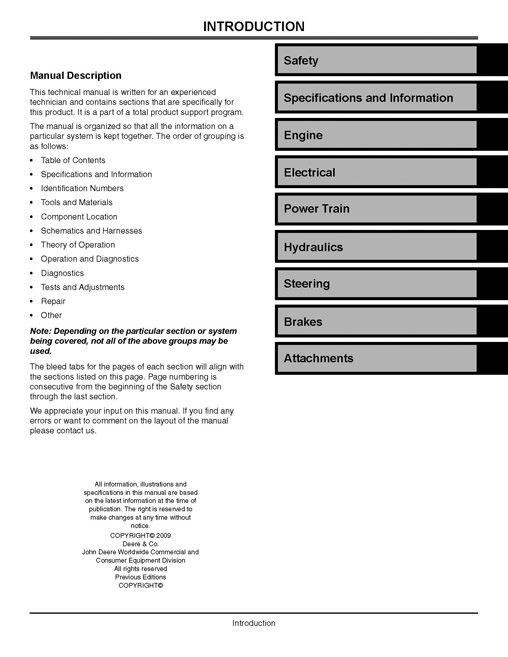
Introduction.
Manual Description.
Safety.
Recognize Safety Information.
Replace Safety Signs.
Handle Fluids Safely – Avoid Fires.
Use Care in Handling and Servicing Batteries.
Use Care Around High-Pressure Fluid Lines.
Use Safe Service Procedures.
Service Tires Safely.
Avoid Injury from Rotating Blades and Drive Shafts.
Service Cooling System Safely.
Handle Chemical Products Safely.
Specifications and Information.
Table of Contents.
General Information.
Metric Fastener Torque Values.
Inch Fastener Torque Values.
Face Seal Fittings with Inch Stud Ends Torque.
Face Seal Fittings with Metric Stud Ends Torque.
O-Ring Face Seal Fittings.
O-Ring Boss Fittings.
Using Proper Fuel (Diesel) – North America.
Diesel Fuel – Europe.
Diesel Fuel Storage.
4-Cycle Diesel Engine Oil – North America.
4-Cycle Diesel Engine Oil – Europe.
Transmission and Hydraulic Oil.
Grease – North America.
Grease – Europe.
Alternative Lubricants.
Synthetic Lubricants.
Lubricant Storage.
Mixing of Lubricants.
Oil Filters.
Diesel Engine Coolant – North America.
Diesel Engine Coolant Drain Interval – North America.
Diesel Engine Coolant – Europe.
Diesel Engine Coolant Drain Interval – Europe.
Identification Numbers.
Serial Number Location.
Machine Identification Number.
Engine Serial Number.
Cutting Unit Serial Numbers.
Engine – Diesel.
Table of Contents.
Specifications.
Engine Specifications.
Torque Specifications.
Tools and Materials.
Tools.
Other Materials.
Component Location.
Starter Components.
Theory of Operation.
Fuel and Air System Operation.
Cooling System Operation.
Lubrication System Operation.
Diagnostics.
Symptom: Engine Will Not Start.
Symptom: Engine Starts but Does Not Continue Running.
Symptom: Low Engine Output.
Symptom: Exhaust Color WHITE Under Load.
Symptom: Exhaust Color BLACK Under Load.
Symptom: Exhaust Temperature Too High.
Symptom: Engine Runs Rough.
Symptom: Excessive Fuel Consumption.
Symptom: Excessive Oil Consumption.
Symptom: Fuel Oil in Crankcase.
Symptom: Coolant in Crankcase.
Symptom: Low Oil Pressure.
Symptom: Engine Is Overheating.
Symptom: Low Engine Coolant Temperature.
Symptom: Low Compression.
Tests and Adjustments.
Test Cylinder Compression.
Adjust Slow Idle.
Adjust Torque Capsule.
Injection Pump Static Timing.
Adjust Valve Clearance.
Check Valve Lift.
Check Connecting Rod Side Play.
Check Connecting Rod Bearing Clearance.
Check Crankshaft End Play.
Check Crankshaft Main Bearing Clearance.
Check Camshaft End Play.
Check Timing Gear Backlash.
Test Fuel Injection Nozzles.
Test Thermostat Opening.
Adjust Fan and Alternator Drive Belt.
Test 48 Volt Generator Belt Tension.
Test Cylinder Leakdown.
Test Cooling System Pressure.
Test Radiator Pressure Cap.
Test Engine Oil Pressure.
Test Air Intake System Leakage.
Adjust Throttle Cable.
Test Fuel System Leakage.
Fuel Transfer Pump Pressure Test.
Fuel Transfer Pump Flow Test.
Bleed Fuel System.
Test Coolant Temperature Switch.
Extending Turbocharger Life.
Turbocharger Seven-Step Inspection.
Check Turbocharger Rotor Shaft Axial Play.
Check Turbocharger Rotor Shaft Radial Play.
Turbocharger Waste Gate Test.
Repair.
Remove and Install Engine.
Remove and Install Rocker Arm Cover.
Remove and Install Rocker Arm Assembly.
Inspect Rocker Arm Assembly.
Remove and Install Cylinder Head and Valves.
Disassemble and Assemble Cylinder Head and Valves.
Inspect Cylinder Head and Valves.
Remove and Install Exhaust Manifold.
Remove and Install Intake Manifold.
Grind Valve Seats.
Lap Valves.
Measure Piston-to-Cylinder Head Clearance.
Remove and Install Piston and Connecting Rod.
Disassemble and Assemble Piston and Connecting Rod.
Inspect Piston and Connecting Rod.
Inspect Cylinder Bore.
Inspect Cylinder Bore Taper and Out-of- Round.
Replace Crankshaft Rear Oil Seal.
Replace Crankshaft Front Oil Seal.
Remove and Install Crankshaft and Main Bearings.
Inspect Crankshaft and Main Bearings.
Remove and Install Crankshaft Gear.
Remove and Install Flywheel.
Remove and Install Camshaft.
Inspect Camshaft.
Remove and Install Camshaft Gear.
Remove and Install Cam Followers.
Inspect Cam Followers.
Remove and Install Timing Gear Cover.
Remove and Install Idler Gear.
Inspect Idler Gear.
Remove and Install Timing Gear Cover Mounting Plate.
Remove and Install Oil Pan, Crankcase Extension, and Strainer.
Remove and Install Oil Pump.
Disassemble and Assemble Oil Pump.
Inspect Oil Pump.
Remove and Install Optional Oil Cooler.
Remove and Install Thermostat.
Inspect Coolant Pump.
Remove and Install Coolant Pump.
Disassemble and Assemble Water Separator.
Remove Fuel Injection Pump.
Install Fuel Injection Pump.
Remove and Install Fuel Injection Nozzles.
Disassemble and Assemble Fuel Injection Nozzles.
Inspect and Clean Fuel Injection Nozzles.
Remove and Install Starting Motor.
Disassemble and Assemble Starting Motor.
Inspect and Test Starting Motor.
Disassemble and Assemble Starter Gear Train.
Disassemble, Inspect, and Assemble Starter Solenoid.
Remove and Install 12V Alternator.
Remove and Install Turbocharger.
Repair Turbocharger.
Prelube Turbocharger.
Electrical.
Table of Contents.
Specifications.
General Specifications.
General Information.
Theory of Operation Information.
Diagnostic Information.
Common Circuit Tests.
Reading Electrical Schematics.
Wire Color Abbreviation Chart.
Conductors for 12-Volt Circuits.
Tools and Materials.
Tools.
Materials.
Component Location.
Electrical Components.
Schematics and Harnesses.
Schematic and Wiring Harness Legend.
Main Electrical Schematic (Sheet 1 of 9).
Command Arm Wiring Harness (W1) Wire Code Table.
Command Arm Wiring Harness (W1) (Sheet 1 of 2).
Main Wiring Harness (W2) Wire Code Table.
Main Wiring Harness (W2) (Sheet 1 of 4).
Reverse Switch Wiring Harness (W7).
Park Brake Switch Wiring Harness (W10).
Down Pressure Kit Y-Wiring Harness (W13) – Optional.
Down Pressure Kit Y-Wiring Harness (W13) Wire Code Table.
Down Pressure Relay Wiring Harness (W14) – Optional.
Down Pressure Kit Relay Wiring Harness (W14) Wire Code Table.
Operation and Diagnostics.
Electronic Control Module Operation.
Electronic Control Module Circuit Test.
Electronic Control Module Checks.
Input Circuit LED Check.
Power Circuit Operation – Unswitched.
System: Power Circuit Diagnosis.
Power Circuit Operation – Switched.
System: Switched Power Circuit Diagnosis.
Interlock Circuit Operation.
System: Interlock Circuit Diagnosis.
Cranking Circuit Operation.
System: Cranking Circuit Diagnosis.
Run Circuit Operation – Operator ON Seat.
System: Run Circuit Diagnosis – Operator ON Seat.
Run Circuit Operation – Operator OFF Seat.
System: Run Circuit Diagnosis – Operator OFF Seat.
Charging Circuit Operation.
System: Charging System Diagnosis.
Cruise Control Circuit Operation.
System: Cruise Control Circuit Diagnosis.
Mow Circuit Operation.
System: Mow Circuit Diagnosis.
4WD Bypass Circuit Operation.
System: 4WD Bypass Circuit Diagnosis.
Backlap Circuit Operation.
System: Backlap Circuit Diagnosis.
Raise-Lower Circuit Operation.
System: Raise-Lower Circuit Diagnosis.
Air Preheater Circuit Operation.
System: Air Preheater Circuit Diagnosis.
Engine Oil Pressure and Hour Meter Circuit.
System: Engine Oil Pressure and Hour Meter Circuit Diagnosis.
Engine Coolant Temperature LED Circuit Operation.
Engine Coolant Temperature Circuit Diagnosis.
Hydraulic Filter Restriction LED Circuit Operation.
System: Hydraulic Filter Restriction Circuit Diagnosis.
Hydraulic Oil Temperature LED Circuit Operation.
System: Hydraulic Oil Temperature Circuit Diagnosis.
Light Circuit Operation.
System: Light Circuit Diagnosis.
Tests and Adjustments.
Diode Pack AMT386 Test.
Ground Circuit Test.
Battery Test.
Charge Battery.
Load Battery Test.
Battery Removal and Installation.
Clean Battery.
Regulated Voltage Output Test.
Starter Loaded Amperage Draw Test.
Starter No-Load Amperage and RPM Test.
Starter Solenoid Test.
Key Switch Test.
Mow-Transport Switch Test.
Seat Switch Test.
Reverse Switch Test.
Backlap Switch Test.
Light Switch Test.
Park Brake Switch Test.
Neutral Switch Test.
Cruise Control Switch Test.
Raise-Lower Switch Test.
Hydraulic Temperature Switch Test.
Engine Oil Pressure Switch Test.
Engine Coolant Temperature Switch Test.
Electrical Relays Test.
Fuel Shutoff Solenoid Test.
4WD Bypass Solenoid Test.
Fuel Pump Test.
Fuse Test.
Diode Test.
Mow Solenoid Test.
Raise-Lower Solenoid Test.
Hydraulic Filter Restriction Switch Test.
Cruise Control Magnet Test.
Air Preheater Test.
Reel Motor Test.
Repair.
WEATHER PACK.
WEATHER PACK.
METRI-PACK.
METRI-PACK.
Electrical E-Cut Hybrids.
Table of Contents.
Specifications.
General Specifications.
Tools and Materials.
Tools.
Materials.
General Information.
Theory of Operation Information.
Diagnostic Information.
Common Circuit Tests.
Reading Electrical Schematics.
Wire Color Abbreviation Chart.
Conductors for 12-Volt Circuits.
Component Location.
Electrical Components.
48 Volt Controller Harness.
Controllers and Reel Motors.
Instrument Cluster Diagnostic Indicators.
Components.
Reel Controller.
Reel Motor.
Schematics and Harnesses.
Schematic and Wiring Harness Legend.
Main Electrical Schematic (Sheet 1 of 8).
Main Wiring Harness (W2) (Sheet 1 of 6).
Main Wiring Harness (W2) Wire Code Table.
Command Arm W1 Wiring Harness.
Command Arm Wiring Harness (W1) Wire Code Table.
W3 48V Power Supply Harness.
48V Power Supply Harness (W3) Wire Code Table.
Reverse Switch.
Park Brake Switch Wiring Harness (W10).
Operation and Diagnostics.
Master Control Module Operation.
Master Control Module Circuit Test.
Master Control Module Checks.
Input Circuit LED Check.
Power Circuit Operation – Unswitched.
System: Power Circuit Diagnosis.
Power Circuit Operation – Switched.
System: Switched Power Circuit Diagnosis.
Interlock Circuit Operation.
System: Interlock Circuit Diagnosis.
Cranking Circuit Operation.
System: Cranking Circuit Diagnosis.
Run Circuit Operation – Operator ON Seat.
System: Run Circuit Diagnosis – Operator ON Seat.
Run Circuit Operation – Operator OFF Seat.
System: Run Circuit Diagnosis – Operator OFF Seat.
Charging Circuit Operation.
System: Charging System Diagnosis.
Cruise Control Circuit Operation.
System: Cruise Control Circuit Diagnosis.
Mow Circuit Operation.
System: Mow Circuit Diagnosis.
Backlap Circuit Operation.
Backlap Circuit Schematic.
System: Backlap Circuit Diagnosis.
Raise-Lower Circuit Operation.
System: Raise-Lower Circuit Diagnosis.
Air Preheater Circuit Operation.
System: Air Preheater Circuit Diagnosis.
Engine Oil Pressure and Hour Meter Circuit.
System: Engine Oil Pressure and Hour Meter Circuit Diagnosis.
Engine Coolant Temperature LED Circuit Operation.
Engine Coolant Temperature Circuit Diagnosis.
Hydraulic Filter Restriction LED Circuit Operation.
System: Hydraulic Filter Restriction Circuit Diagnosis.
Hydraulic Oil Temperature LED Circuit Operation.
System: Hydraulic Oil Temperature Circuit Diagnosis.
Light Circuit Operation.
System: Light Circuit Diagnosis.
Electronic Controllers.
Data Bus Systems.
CAN Bus Theory of Operation.
CAN Bus Message Structure.
CAN Network Voltage Checks.
Troubleshooting Electronic Controllers.
Accessing Addresses and Diagnostic Trouble Codes.
Approved Software for Control Units.
RMC and Motor Diagnostics.
Electronic Controllers Theory of Operation.
Reel Motor Theory of Operation.
Reel Motor Controller Signals.
Reel Motor Signals.
Reel Motor Safety Interlock Operating Conditions.
Reading Reel Controller Fault Codes (Onboard Controller Blink Code Display).
Fault Codes and DTC Relationship (Display Panel).
Error Codes Table.
RMC_000628.12 (Blink Code SOLID ON) – Stuck in Boot Block.
RMC_002513.03 (Blink Code 7-3) – Orange Phase (A) is Shorted to Supply.
RMC_002513.04 (Blink Code 7-2) – Orange Phase (A) is Shorted to Ground.
RMC_002513.05 (Blink Code 7-4) – Orange Phase (A) is Open.
RMC_002514.03 (Blink Code 7-3) – Black Phase (B) is Shorted to Supply.
RMC_002514.04 (Blink Code 7-2) – Black Phase (B) is Shorted to Ground.
RMC_002514.05 (Blink Code 7-4) – Black Phase (B) is Open.
RMC_002515.03 (Blink Code 7-3) – Green Phase (C) is Shorted to Supply.
RMC_002515.04 (Blink Code 7-2) – Green Phase (C) is Shorted to Ground.
RMC_002515.05 (Blink Code 7-4) – Green Phase (C) is Open.
RMC_003509.00 (Blink Code 7-5) – Pot Signal Voltage High.
RMC_003509.01 (Blink Code 7-5) – Pot Signal Voltage Low.
RMC_003510.00 (Blink Code 9-7) – Pot Supply Voltage High.
RMC_003510.01 (Blink Code 9-7) – Pot Supply Voltage Low.
RMC_003511.00 (Blink Code 9-5) – Hall Voltage High.
RMC_003511.01 (Blink Code 9-5) – Hall Voltage Low.
RMC_003597.00 (Blink Code 9-3) – Controller 14V High.
RMC_003597.01 (Blink Code 9-3) – Controller 14V Low.
RMC_521153.00 (Blink Code NONE) – System reaction monitor, not a fault. Used for internal data collection..
RMC_521153.15 (Blink Code 2-9) – Controller Shutdown Over Temp.
RMC_522327.00 (Blink Code 2-10) – Motor Over Temp.
RMC_522917.00 (Blink Code 2-5) – Controller Current Threshold 3 Shutdown.
RMC_522917.06 (Blink Code 2-8) – Controller Hardware Current Shutdown.
RMC_522917.15 (Blink Code 2-5) – Controller Current Threshold 1 Shutdown.
RMC_522917.16 (Blink Code 2-5) – Controller Current Threshold 2 Shutdown.
RMC_522918.00 (Blink Code 1-5) – Motor Start Failed 3x Fault.
RMC_522918.02 (Blink Code 1-10) – Motor Spin Direction Shutdown.
RMC_522918.15 (Blink Code 1-6) – Motor Stalled While Running.
RMC_522919.02 (Blink Code NONE) – System reaction monitor, not a fault. Used for internal data collection..
RMC_522919.03 (Blink Code 6-6) – Hall Resync Shutdown.
RMC_522919.04 (Blink Code NONE) – System reaction monitor, not a fault. Used for internal data collection..
RMC_522919.08 (Blink Code NONE) – System reaction monitor, not a fault. Used for internal data collection..
RMC_522919.09 (Blink Code NONE) – System reaction monitor, not a fault. Used for internal data collection..
RMC_522919.12 (Blink Code 6-4) – Invalid Hall State Detected at Start-Up.
RMC_523666.00 Bus Voltage High (Blink Code 9-2).
RMC_523666.01 Bus Voltage Low (Blink Code 1-7).
RMC_523666.02 Low VBUS on Start (Blink Code 1-7).
RMC_523666.15 (Blink Code – NONE) System reaction monitor, not a fault. Used for internal data collection..
Observed Symptoms.
Marcelling.
Striping.
Height-of-Cut Changes.
Poor Quality of Cut.
Reel Does Not Rotate.
Unit Not Cutting.
Tests and Adjustments.
Interlock Module Check.
Ground Circuit Test.
Battery Test.
Charge Battery.
Battery Load Test.
Regulated Voltage Output Test.
Starting Motor Cranking Amperage Draw Test.
Starter No-Load Amperage and RPM Test.
Starter Solenoid Test.
Fuse Test.
Diode Test.
Relay Test.
Key Switch Test.
Park Brake and Mow-Transport Switch Test.
Neutral Switch Test.
Cruise Control Switch Test.
Raise-Lower Switch Test.
Seat Switch Test.
Raise or Lower Solenoid Test.
Hydraulic Temperature Switch Test.
Hydraulic Filter Restriction Switch Test.
Fuel Shutoff Solenoid Test.
Fuel Pump Test.
Engine Oil Pressure Switch Test – Diesel Engine.
Engine Coolant Temperature Switch Test.
Headlight Switch Test (Optional).
Air Preheater Test.
Cruise Control Magnet Test.
Reel Speed Potentiometer Test.
Backlap Switch Test.
Reel Motor Forward-Reverse Switch Test.
48V Alternator Voltage Output Test.
48V Alternator Current Output Test.
Diode Pack AMT386 Test.
Reel Motor Test.
Reel Motor Wiring.
Repair.
Remove and Install Battery.
Clean Battery.
Remove METRI-PACK.
Replace METRI-PACK.
Remove WEATHER PACK.
Repair Reel Motor Wiring Harness.
Hydrostatic Power Train.
Table of Contents.
Specifications.
General Specifications.
Repair Specifications.
Torque Specifications.
Tools and Materials.
Tools.
Materials.
Component Location.
Component Location – Two Wheel Drive.
Component Location – Four Wheel Drive.
Hydrostatic Schematics.
Neutral – Two Wheel Drive.
Forward – Two Wheel Drive.
Neutral – Four Wheel Drive.
Forward – Four Wheel Drive.
Theory of Operation.
Hydrostatic Transmission.
Diagnostics.
Troubleshooting Hints.
Symptom: Mower Will Not Move in Forward or Reverse.
Symptom: Mower Will Not Reach Full Speed.
Symptom: Sluggish Response to Acceleration or Deceleration.
Symptom: Hydrostatic System Operating Hot.
Symptom: Noisy Pump.
Tests and Adjustments.
Test Hydrostatic System Relief Pressure.
Test Charge Pressure – Static.
Test Charge Pressure – Dynamic.
Test Hydrostatic Transmission Pump Flow.
Adjusting Mow and Transport Speeds.
Test and Adjust Transmission Neutral Position.
Repair.
Remove Hydrostatic Pump.
Disassemble Hydrostatic Pump.
Inspect Hydrostatic Pump.
Assemble Hydrostatic Pump.
Install Hydrostatic Pump.
Remove and Install Front Wheel Motor.
Disassemble and Inspect Wheel Motor.
Assemble Wheel Motor.
Wheel Motor Final Checks.
Remove Rear Wheel Motor (Four Wheel Drive).
Install Rear Wheel Motor (Four Wheel Drive).
Remove Four Wheel Drive Valve.
Disassemble Four Wheel Drive Valve.
Inspect Four Wheel Drive Valve.
Assemble Four Wheel Drive Valve.
Install Four Wheel Drive Valve.
Start-Up Procedure.
Hydraulics.
Table of Contents.
Specifications.
General Specifications.
Test and Adjustment Specifications.
Torque Specifications.
Tools and Materials.
Tools.
Component Location.
Reel Mower Circuit Component Location – 7500, 7700, 8500, 8700.
Rotary Mower Circuit Component Location – 8800.
Backlapping Valve Component Location – 7500, 7700, 8500, 8700.
Reel Lift Circuit Component Location.
Rotary Deck Lift Circuit Component Location.
Schematics and Harnesses.
JIC Hydraulic Circuit Symbols.
Hydraulic Schematic – 7000 Series Precision Cut.
Hydraulic Schematic – 8000 Series Precision Cut.
Hydraulic Schematic – 7500.
Hydraulic Schematic – 8800 Precision Cut.
Operation and Diagnostics.
Reel Drive System Theory of Operation – 7500, 7700, 8500, 8700.
Rotary Mower Drive System Theory of Operation – 8800.
Lift System Theory of Operation.
System: Reel Drive Troubleshooting.
System: Rotary Mower Drive Troubleshooting.
System: Lift System Troubleshooting – All Machines.
Tests and Adjustments.
Bleed Hydraulic System.
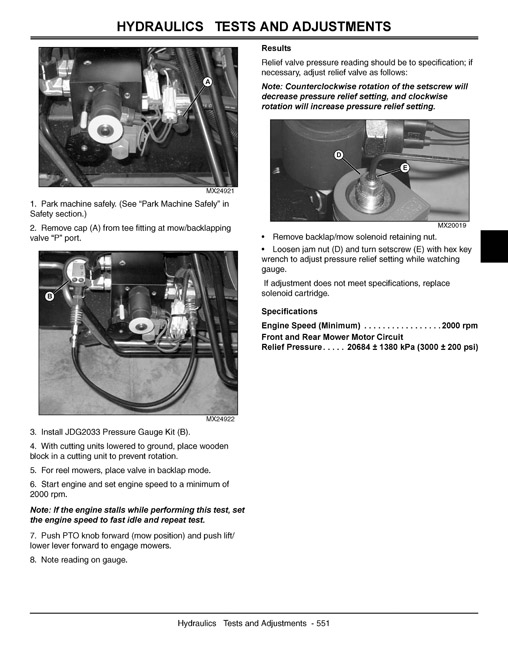
Test Front and Rear Mower Circuit Relief Pressure (all except 7500-E, 8500-E).
Test Reel Circuit Pump Flow – 7000 and 8000.
Test Rotary Mower Circuit Pump Flow – 8800.
Test Cutting Unit Motor Case Drain.
Test Lift System Relief Pressure.
Check and Adjust Wing Cutting Units Upstop.
Test Lift and Steering Pump Flow.
Test Lift System Leakage.
Test Optional Down Pressure Valve.
Repair.
Remove and Install Lift Valve.
Disassemble, Inspect, and Assemble Lift Valve.
Remove Lift Arm.
Remove Lift Arm Bushing.
Install Lift Arm Bushing.
Install Lift Arm.
Remove and Install Front Lift Cylinder.
Remove and Install Center Front Lift Cylinder (7500.
Remove and Install Front Wings Lift Cylinder (7500.
Remove and Install Rear Lift Cylinder.
Inspect Wing Lift Arms Upstop and Linkage.
Remove and Install Upstop.
Remove and Install Rear Lift Cylinder Flow Restrictor.
Remove and Install Front Center Lift Cylinder Flow Restrictor.
Remove and Install Rear Lift Cylinder Lost Motion Linkage.
Remove and Install Triple Pump (except E models).
Disassemble Triple Pump.
Assemble Triple Pump.
Remove and Install Reel Motor QA-5.
Remove and Install Reel Motor QA-7.
Disassemble and Assemble Motor – QA-5.
Disassemble and Assemble Motor QA-7.
Remove and Install Backlapping Valve – 7000 and 8000.
Disassemble, Inspect, and Assemble Backlapping Valve – 7000 and 8000.
Disassemble, Inspect, and Assemble Mow Valve – 8800.
Steering.
Table of Contents.
Specifications.
Test and Adjustment Specifications.
Tools and Materials.
Tools.
Component Location.
Steering Components.
Theory of Operation.
Steering System.
Diagnostics.
Symptom: Steering Wanders.
Symptom: Steering Shimmy.
Symptom: Sluggish Steering Response.
Symptom: Excessive Steering Wheel Free- Play.
Symptom: High Steering Effort in One Direction.
Symptom: High Steering Effort in Both Directions.
Symptom: Steering Cylinder Will Not Fully Extend or Retract.
Tests and Adjustments.
Test Steering System Leakage.
Test Steering Control Unit (SCU) Leakage.
Test Steering System Relief Pressure.
Repair.
Remove and Install Steering Control Unit (SCU).
Brakes.
Table of Contents.
Specifications.
General Specifications.
Torque Specifications.
Theory of Operation.
Brake System.
Diagnostics.
Symptom: Park Brake Does Not Hold.
Symptom: Excessive Brake Wear.
Symptom: Brakes Do Not Release.
Symptom: Brake Pedal Does Not Return.
Symptom: Brakes Noisy.
Tests and Adjustments.
Adjust Park Brake.
Repair.
Replace Brake Pads.
Attachments.
Table of Contents.
Specifications.
Cutting Units.
General Specifications.
Adjustment Specifications – QA-5 and QA-7 Reels.
Repair Specifications – Rotary Deck.
Torque Specifications.
Tools and Materials.
Special or Essential Tools.
Dealer-Fabricated Tools.
Other Materials.
Component Location.
Cutting Unit QA-5.
Cutting Unit QA-7.
Fairway Tender Conditioner (FTC).
Verticut QA-5.
Verticut QA-7.
Rotary Cutting Deck.
Theory of Operation.
Reel and Bed Knife Grinding.
Vertical Cutting Unit.
Rollers.
Performance Variables.
Diagnostics – Reel Mowers.
Marcelling.
Streaking.
Height-of-Cut Changes.
Poor Quality of Cut.
Reel Does Not Rotate.
Unit Not Cutting.
Diagnostics – Rotary Mowers.
Mower Deck Cuts Unevenly.
Mower Deck Vibrates Excessively.
Excessive Noise from Mower Deck.
Tests and Adjustments.
Backlapping and Bed Knife-to-Reel.
Adjust Reel Speed.
Backlapping Procedure.
Adjust Height-of-Cut Range QA-5 Reel.
Adjust Height-of-Cut (HOC) – QA-5 Reel.
Adjust Front Roller – QA-5 Reel.
Adjust Cutting Unit Shield QA-5.
Adjust Bed Knife to Reel Clearance QA-5.
Adjust Height-of-Cut Range QA-7.
Adjust Height-of-Cut (HOC) QA-7.
Adjust Front Roller QA-7.
Adjust Cutting Unit Shield QA-7.
Adjusting Grass Deflector QA-7.
Adjust Reel-to-Bed Knife Clearance QA-7.
Adjusting Fairway Tender Conditioner.
Adjust Depth-of-Cut – Vertical Cutting Units.
Adjust Rear Roller Power Brush.
Adjust Height-of-Cut (HOC) Rotary Deck.
Repair – Reel Units.
Remove and Install Cutting Unit.
Motor Orientation.
Remove and Install Front Roller – QA-5 Reel.
Remove and Install Rear Roller – QA-5 Reel.
Remove and Install Bed Knife – QA-5 Reel.
Remove and Install Reel – QA-5 Reel.
Rotating Reel Cutting Units.
Remove and Install Front Roller QA-7.
Remove and Install Reel QA-7.
Remove and Install Bed Knife QA-7.
Removing and Installing Bed Knife and Shoe QA-7.
Repair Front Roller.
Remove and Install Fairway Tender Conditioner.
Disassemble and Inspect Fairway Tender Conditioner.
Remove and Install Power Brush.
Repair – Rotary Decks.
Remove and Install Rotary Decks.
Remove and Install Blades.
Sharpen Blades.
Balance Blades.
Remove and Install Front Rollers.
Repair Front Roller Assembly.
Remove and Install Rear Roller.
Repair Rear Roller Assembly.
Remove and Install Spindle Housing.
Repair Spindle.
Index.


Reviews
There are no reviews yet.